contact microphones
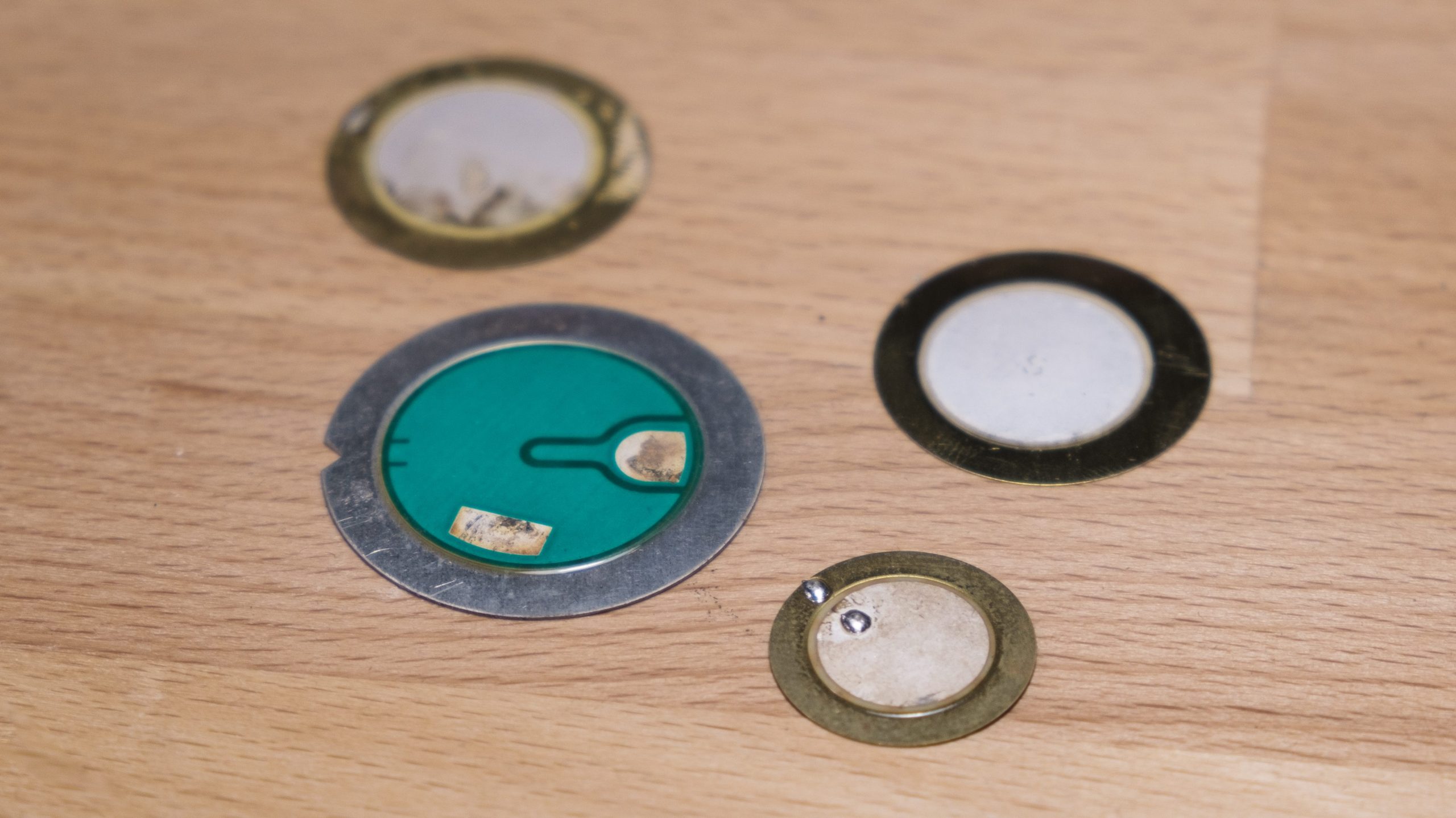
Piezo crystal generates a voltage when deformed or bent. It is commonly used as a thin piezoelectric ceramic round glued to a thin brass or alloy metal disc. This center disc is positively charged while the brass disc is negatively charged. The voltage can be measured across those parts and then amplified to produce sound.
The reverse is also true. Send an amplified signal to a piezoelectric crystal and it will produce tones. They can also reproduce complex sounds, but have a limited frequency range.


A contact microphone is a small flat piezo disk/element that translates physical surface vibrations into voltage. The piezo discs are a layer of crystal in the center of a thin brass disk. When there is a vibration on a surface of an object, the disc bends slightly which generates a (small) electrical signal.
piezo disks as microphones
Contact microphones are commonly used to amplify acoustic guitars, pianos, and other acoustic instruments. On their own they produce an extremely high impedance signal which is greatly enhanced by using a high impedance pre-amp like a radial or a red-eye box. You can also build your own preamplifier for a fraction of the cost.
In addition to amplifying musical instruments, contact microphones are often used in creating foley sounds for film and video. Here are a few examples of piezos used as microphones…
Recording a variety of sounds use contact microphones — with background music 🤔
outdoor experiments with a contact mic
contact microphones as sensors
Contact microphones can also be used as sensors that send data to computers or microcontrollers to control media or trigger processes. To connect a contact mic to a microcontroller like an Ardiuno, connect the + wire to 5V, connect the – wire to the analog pin A0, and connect a 10k resistor from the – leg to ground, as seen in the picture below.

/*
  Analog Input
 Demonstrates analog input by reading an analog sensor on analog pin 0 and
 turning on and off a light emitting diode(LED)  connected to digital pin 13.
 The amount of time the LED will be on and off depends on
 the value obtained by analogRead().

 The circuit:
 * Potentiometer attached to analog input 0
 * center pin of the potentiometer to the analog pin
 * one side pin (either one) to ground
 * the other side pin to +5V
 * LED anode (long leg) attached to digital output 13
 * LED cathode (short leg) attached to ground

 * Note: because most Arduinos have a built-in LED attached
 to pin 13 on the board, the LED is optional.


 Created by David Cuartielles
 modified 30 Aug 2011
 By Tom Igoe

 This example code is in the public domain.

 http://arduino.cc/en/Tutorial/AnalogInput

 */

int sensorPin = A0;    // select the input pin for the potentiometer
int ledPin = 13;      // select the pin for the LED
  // Pin 13: Arduino has an LED connected on pin 13
  // Pin 11: Teensy 2.0 has the LED on pin 11
  // Pin  6: Teensy++ 2.0 has the LED on pin 6
  // Pin 13: Teensy 3.0 has the LED on pin 13
int sensorValue = 0;  // variable to store the value coming from the sensor

void setup() {
  // declare the ledPin as an OUTPUT:
  pinMode(ledPin, OUTPUT);
}

void loop() {
  // read the value from the sensor:
  sensorValue = analogRead(sensorPin);
  // turn the ledPin on
  digitalWrite(ledPin, HIGH);
  // stop the program for <sensorValue> milliseconds:
  delay(sensorValue);
  // turn the ledPin off:
  digitalWrite(ledPin, LOW);
  // stop the program for for <sensorValue> milliseconds:
  delay(sensorValue);
}
piezo disks as lofi speakers

contact microphones in practice…
Additional Resources
- http://www.contactmicrophones.com/
- http://www.instructables.com/id/Make-a-Contact-Microphone/
- http://makezine.com/projects/make-38-cameras-and-av/piezo-contact-mic/
- http://www.musicofsound.co.nz/blog/the-first-rule-of-contact-mic-club