
This project uses cheap integrated circuits called hex schmitt triggers to generate sound and light. Each little chip can output six square wave signals, which can be amplified, tuned, and modulated using basic electrical components. Sound artists have been using these chips for decades to simple noisy synthesizers, installations, and performances. This module walks you through building a simple square wave synthesizer and collects my favorite resources, links, and examples related to this type of circuit.
square waves

A square wave is an electrical signal that alternates between on and off, or full voltage (high) and no voltage (low). If this oscillation happens at a frequencies greater than 20Hz (20 oscillations per second) we can connect it to a speaker to produce an audible tone. Using resistors and a capacitors we can control the frequency of this tone. One Hex Schmitt Trigger IC can produce six seperate oscilator tones! Meaning, from a single $1 chip we can get 6 voice polyphony, a small swarm of aggressive buzzing electro bees. There are various ways to soften the edges of the square waves using filter and modulation circuits, but first we’ll focus on producing basic chiptune-esque tuneable square waves.
components
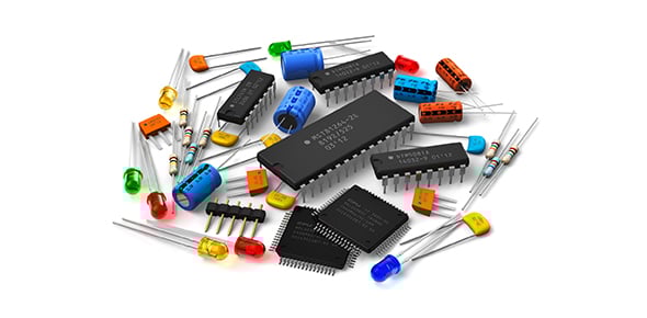
To start, you will need a few basic components that can be found at all electronics stores. This module does not go into detail about the function of every component, but read through this page on basic electronics — it is a wonderful primer on diy electronics and basic components and principles. The components for this project are relatively inexpensive. Including the reusable breadboard and a speaker (optional), you can probably get everything you need for around $20-25.

A breadboard will let you experiment with different component values and connect components together without soldering. It makes testing and prototyping quick and easy and can be reused on your next circuit design projects as well. Find more information about breadboards here.
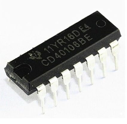
The chip we’ll be using for our synth is the CD40106. (datasheet, PDF) which is a hex inverter with hysteresis, also known as a Hex Schmitt Trigger. It works with a wide range of voltages, but we’ll be using it primarily with 9V batteries. If you’re interested, this page has a good simple explanation of hysteresis.

Photoresistors, also called Light Dependant Resistors (LDRs), are a passive component whose resistance changes based on the amount of light that on the component’s surface. They are cheap and a lot of fun, but hard to control with any precision.

Potentiometers can be used as either variable resistors (like LDRs) or voltage dividers. They allow you to smoothly and precisely adjust the amount of resistance (or voltage) in a circuit. We’ll use them as pitch and volume controls, but you might find other uses for them as well!

Pushbuttons are simple components that simply make and break connections, letting you turn things on and off. There are different kinds of pushbuttons, but we’ll primarily be using momentary buttons which make a connection while the button is depressed and break the connection when it is released.

Toggle switches are a lot like buttons, but instead of momentarily making a connection they hold the connection closed or open, making or breaking the circuit. Toggles work well as power switches and are useful for turning part of your synthesizer on and off. They can also be used to switch where your signal goes
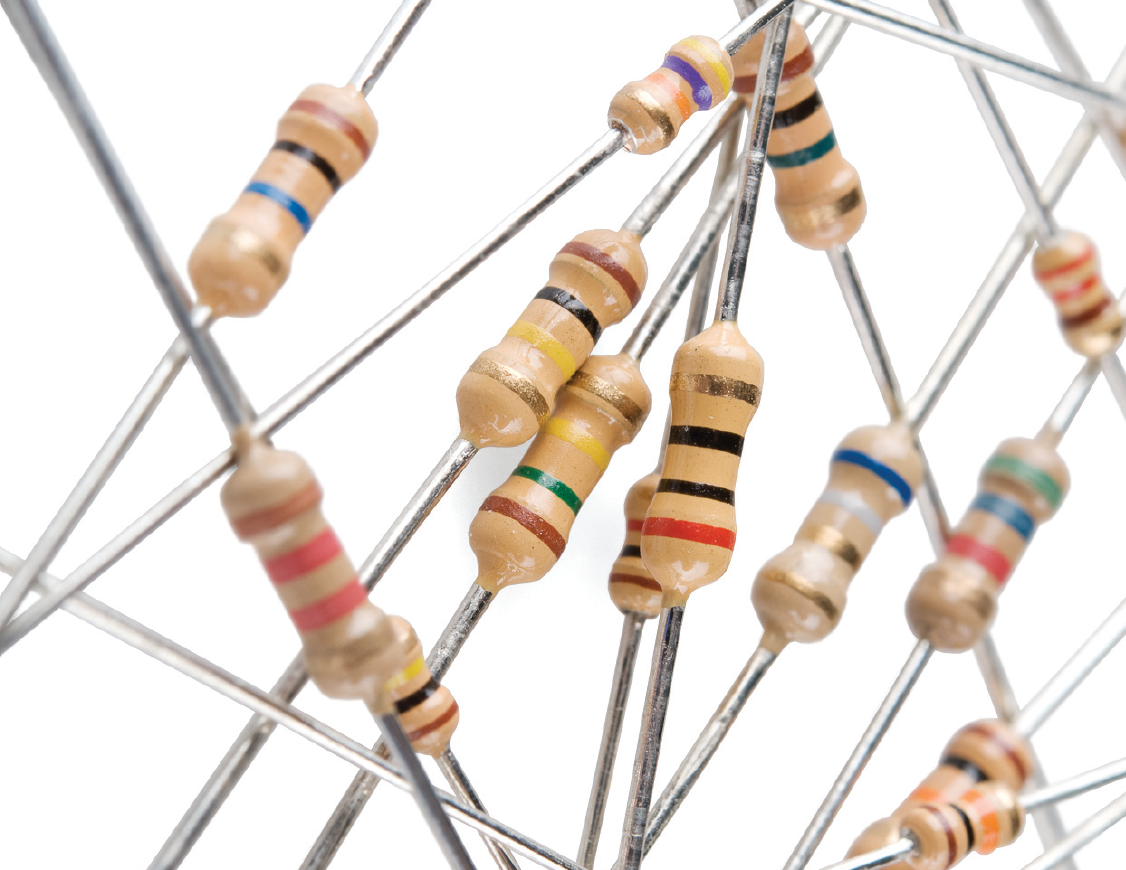
Resistors are one of the most common (and cheap) electronic components. They limit the current flowing through your circuit, slowing down the flow of electrons. Resistors are used in countless ways, and we’ll use a bunch of them in building our synthesizers.

Capacitors store and discharge energy, allowing you to create periodic behavior. Capacitors come in two main varieties, ceramic capacitors (smaller storage, non-polar) and electrolytic capacitors (larger potential storage, polarized). We’ll talk more about polarized vs. non-polarized components later.

Battery clips simply allow you to connect a battery to your circuit. Be very careful when connecting your battery, if you accidentally attach your battery backwards you could ruin your chip. Take your time when connecting your battery (and buy a few extra chips).

A 1/4″ output jack will let you connect your synthesize to an amplifier, mixer, or effects processor/guitar pedal. If you plan on connecting your synth to a little bluetooth speaker or something with an aux input, you might consider using an 1/8″ jack instead.
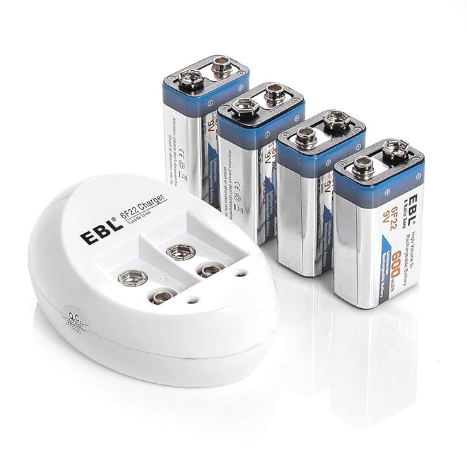
We’ll be using standard 9V batteries for this project. I highly recommend investing in a couple rechargeable batteries. They will quickly save you money and battery waste is extremely toxic to the environment. Rechargeable energy! A pair of rechargeable batteries costs around $25 and will last you for years. Again, be careful to connect your battery to the clip correctly.
Optional Components

Adding a little amplifier chip to your circuit will let you to connect a speaker for a self contained synth. There are lots of cheap readymade amplifier boards for a few dollars, but the cheapest solution by far is the LM386 audio amplifier IC. There is an entire page of information on amplification options.

If you are using a built in amplifier, you’ll need a speaker component as well. Speakers range from a couple of dollars (pictured) to very expensive. For our purposes, a cheap speaker will do just fine. I like building synthesizers right into cheap old speakers. They sound great and it’s a readymade enclosure — all about that reanimation.
additional resources
Also, here are a bunch of resources on building hex schmitt synthesizers. Use them for reference and/or inspiration. “Simple Synthesizers” is the little synth zine I typically hand out during workshops, but the most up-to-date information will be on this webpage.
- Simple Synthesizers (pdf)
- Handmade Electronic Music (pdf)
- Logic Noise (webpage)
- CMOS Cookbook (pdf)
- Electronics Projects for Musicians (pdf)
- Sea Moss
This project generates sound and light using hex schmitt trigger integrated circuits (CD40106). For a detailed understanding of how these chips work, I recommend reading Elliot Williams’ article on Hackaday called Logic Noise: Sweet Sweet Oscillator Sounds. Each chip can output six square wave oscillators, which can be amplified, tuned, and modulated using basic components.
These circuits can be easily soldered onto proto-board. There are also a few cheap and customizable pcb boards specifically designed for this type of synthesizer. In addition to standard controls like buttons and knobs, you can experiment with controlling the circuit using light, temperature, pressure, orientation, and stretchiness, among other things. You can go deep with the electronics and build modulating drone generators and noisy sequencers or you the circuit to get into the sculptural, critical, and theatrical potentials of interfacing with electrons.
breadboard review
Let’s start with the breadboard. Breadboards are great tools for prototyping circuits. You can plug components right into the holes without having to solder them. It is important to understand how a breadboard works…

In the breadboard above, all the holes in the green rows are connected and all the holes in the blue rows are connected. Let’s call the long rows on the sides “buses”. The buses run perpendicular to the rows and they bring power (+) and ground (-) up and down your breadboard. The middle grey space between the blue and green rows breaks the connection between the blue and green sections. It is also conveniently the perfect size for placing an IC chip across that middle gap. Let’s start by placing our Hex Schmitt IC on the breadboard like this…
the basic circuit

Also, add two wires between the positive and negative rails on either side of the board. This will allow us to connect power to one side of the breadboard and be able to access it on both sides. Note the subtle notch in the chip and be sure to point that to the left. The numbers don’t really matter and they might get confusing if people have different types of breadboards, just focus on the general orientation for now. This particular IC chip is a 6 voice hex inverter circuit. The pinouts for the chip are as follows…

Starting at the notch, the pin directly left of the notch is pin 1, and the numbering continues in a horseshow end with pin 14 at the right side of the notch. This numbering system is true for most ICs. Looking at the pinouts above, note which pins are pairs (1&2, 3&4, etc). Each of these pairs will create one our synthesis voices. Pin 14 (+) is the power pin, where we give the chip power, and Pin 7 (-) is the ground pin, which connects to ground. Let’s add power and ground to our chip…

Next we’ll add a 10K resistor, a small capacitor, and a photocell to complete one voice of our synthesizer. All three of these components work together to produce the tone. The capacitor is a component that periodically stores and discharges electrons which triggers the IC to switch between high and low states. The size of the capacitor determines the range of frequencies for that voice of the synthesizer. The photoresistor changes the rate at which the capacitor charges, and will be how you dynamically change the frequency of the square wave (within the range set by the capacitor). The fixed 10K resistor conditions the output signal to send to an amplifier or powered speaker. Add the 10K resistor, small capacitor, and a photocell as pictured below using pins 3&4 on the IC to give us plenty of room…

In order to hear the tone we need to add power to our bread board and add a jack that allows us to connect our circuit to a speaker. Once you’ve added those components, connect a guitar cable between your powered speaker and the output jack and cover your ears.

We just went through a breadboard diagram for this synthesizer circuit, but if things get more complicated, we’re going to need another method for describing a circuit. Enter the dreaded/loved circuit schematic!

This is the exact same circuit as above, but in a modified schematic form (click to enlarge).
In the next sections we will look at adding voices and volume control.